how to draw gear in autocad 3d
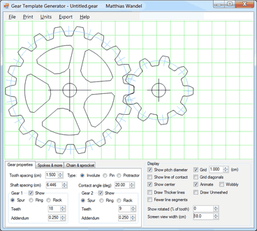 | Gear template generator helpThe gear template generator is a plan to calculate and impressgear shapes for involute spur and pinwheel gearing. |
Gear ratio
I have had numerous requests to make the gear program brandish the gear ratio. The reason the program does not explicitly display the gear ratio is that the gear ratio is whatever you enter. For instance, if you have a tooth count of 7 and 12, the gear ratio is 7:12. That is to say, the 7-molar gear volition turn 12 times for every 7 turns of the 12-tooth gear. Similarly, a ten-tooth with a 30-tooth gear will have a gear ratio of 30:10, which tin can also be expressed as 3:1.Compounded gear rations (more ii gears)
The gear program will show two gears so you can come across how the gears mesh. Gears just mesh two at a time. If y'all need to blueprint a gear railroad train with more than 2 gears, you lot need to determine what gear pairs you need, so utilise the gear program to generate the gears. Working out chemical compound gear ratios is not something the gear programme volition do for you, just the question comes upwards frequently plenty that it makes sense to explain here.
For example, if you want a 1:ten reduction, merely you lot don't desire a gear smaller than nine teeth (smaller gears can run crude) you could make a 9 and a ninety tooth gear. Merely 90 tooth is a very large gear. Instead, you could make a ten:thirty reduction, followed by a nine:30 reduction. Multiplying those together will give you 90:900, which is a ane:10 ratio. How to come up up with these numbers? Meet below.
Example: designing a 1:12 reduction for a clock
If you want to build a clock, yous will need a final 1:12 reduction. Lets say minimum vii teeth, so express it every bit 7:84. Now imagine we put a 24 molar gear betwixt the seven and the 84. The 7:84 ratio is notwithstanding intact. Then we have vii:24 followed past 24:84. Lets split the number of teeth on 24:84 pair past iii (this won't modify the ratio), so we have 8:28. So a seven:24 and 8:28 pair volition give the desired reduction. To check, multiply out: 7x8:24x28 is 56:672, Split up both sides by 56 gives 1:12.
Yet, if the teeth of both pairs are the same size, the 7:24, having fewer teeth, will accept a smaller shaft spacing than the viii:28. But you tin just enter the shaft spacing, and the gear program will adjust the gear tooth size accordingly, then the 8:28 pair will have slightly smaller teeth.
More than about gear ratios
Gear type and properties
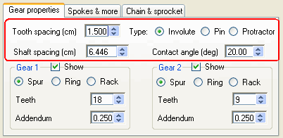
Tooth spacing
Specifies the center to center tooth spacing, as measured along the gear'due south pitch diameter.
Blazon
This selects what type of gear teeth to depict. The gear's teeth can be spur, pinwheel, or protractor.
Involute
This specifies involute spur gears. Involute spur gears are the most ordinarily used type of gear. Any two gears that have the same tooth spacing (or pitch) and the same contact angle (too known as pressure level angle) will mesh and run smoothly.
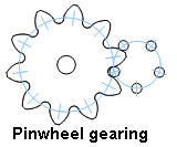
Pivot
For some applications, information technology is desirable that ane gear be comprised of just a band of pins. Such gears are as well known every bit "lantern" gears. The pins are typically held together by two discs on either side, so that the whole structure could exist said to look like a "lantern". Such a gear may or may not have a shaft passing through the centre of the pins.
The primary advantage of this blazon of gear is that it's possible to brand gears with as few equally iii teeth that will still run smoothly.
For pinwheel gearing, the gear on the right volition always be the pinwheel and the gear on the left volition e'er be cycloid shaped to mate with the pinwheel.

Protractor
Sometimes information technology'due south useful to exist able to create a template that divides a circle into a specific number of intervals. For case, to divide a circle into 23 equal parts with a protractor would be tedious and fault prone. Using this program you tin can print a template that divides the circle as specified.
Shaft spacing
This field always displays the calculated shaft spacing value. The shaft spacing is the sum of the pitch radii of both gears. Pitch radius is calculated from the pitch circumference. Pitch circumference is equal to the number of teeth times the tooth spacing.
Y'all can too enter a new value in this field and the gear's tooth spacing will automatically be recalculated to produce the desired center to center distance for the two gears.
Contact angle
This field specifies the contact angle, besides known equally pressure angle, for involute spur gears. Larger contact angles produce gears that accept more triangular looking teeth. Larger contact angles work better for gears with a modest number of teeth, only the overall issue is lower efficiency due to higher friction in the gear set.
This field is simply applicable for involute spur teeth and is hidden if other types of gear teeth are selected.
Pin diameter
This field specifies the size of the pins for pinwheel gearing. This field is only applicable to pinwheel gearing and is subconscious if other types of gear teeth are selected.
Gear properties
 This department allows y'all to specify the parameters specific to each gear.
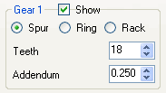
 Show
Selects whether the gear is visible. Note that for pinwheel gears, the backdrop of the pinwheel affect the shape of the mating gear, so even if the right gear is hidden, its properties still affect the gear on the left.
Spur
Selects a regular spur gear. That is, a round gear with teeth on the outside.
Ring
Selects a band gear. A band gear is a gear with teeth on the inside. Band manner tin only be selected if the other gear is a spur gear. Band gears are useful when making planetary gear sets
Rack
Selects a "rack" type gear. A rack is essentially a gear that has been unwrapped. Rack and pinion mode is only currently available for anfractuous molar types.
Teeth
Specifies the number of gear teeth.
Odd shaped gears generated past setting the correct side gear addendum to zip.
Addendum
Specifies the annex of the teeth. The annex is how much the gear tooth protrudes exterior its pitch diameter. It is specified relative to the tooth spacing. That is, a setting of 0.25 means that a tooth'due south addendum will be one quarter of the spacing, or virtually half of its width.The gear's dedendum (that is, how deep a cut beyond the pitch circle between teeth) is taken from the mating gear's addendum. So to set the dedendum of a gear, just set the corresponding annex of the mating gear.
Note that cycloid gears don't use the addendum parameters.
Spokes & more tab
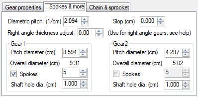
Diametric pitch
Some people adopt to use diametric pitch, equally opposed to tooth spacing (besides known as circumferential pitch). Diametric pitch is equal to the gear's molar count divided by the pitch diameter, so this number varies inversely with tooth size. Please note that version 2 and earlier of the gear generator calculated this as bore per tooth (inverse of what it should be). You can enter a value in the diametric pitch, and the circumferential pitch on the main tab volition automatically exist updated.
Slop
The amount of total slop, play, or tolerance. With slop set to goose egg, the gears are printed so that they fit exactly, with no tolerance for slop. Usually, the width of the cut on the bandsaw or ringlet saw volition provide enough slop, but you can also add slop by setting this parameter.
Right angle thickness arrange
When making 90 degree gearing, with your saw tabular array tilted by the gear's contact angle, this field is used to tell the gear program how thick your material is, so that the teeth tin exist "fattened" past the right amount so that the bevel cut will result in gears of the right thickness. This parameter is ONLY used for involute spur gears.
Please run into my commodity on right angle gearing on how to utilise this. This feature was added for version 3.i.0 (Feb 2015). If you accept an earlier version 3.0.x, click on "help" in the program to get the latest version.
Pitch bore
The pitch bore is the diametric pitch times the number of teeth. The pitch bore is useful for working out gear spacing. The ideal center to center distance of a pair of gears is equal to the sum of the pitch diameters, divided by two. Note that the shaft spacing in the "Gear properties" tab already shows the middle to eye distance as "shaft spacing".
Overall diameter
This displays the overall bore of the gear, from tip to tip.
Spokes
Specifies the number of spokes. Only spur gears higher up a sure number of teeth are large enough to have spokes.
Shaft pigsty diameter
Specifies the shaft pigsty to draw. For pinwheel (lantern) gears, this specifies the size of the shaft in the heart of the pins. The gear teeth of the mating gear will be kept short plenty so as not to interfere with the central shaft. Specify zippo to omit the center shaft or shaft hole.
Concatenation & Sprocket way
The gear template generator version 2.0 includes a "chain and sprocket" fashion. This mode is intended to assist in generating sprocket shapes for wooden block chains and roller chains.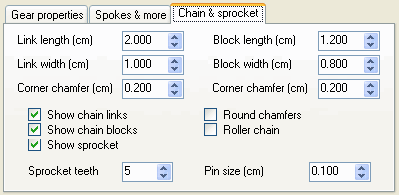 Concatenation & sprocket mode is turned on by selecting the "Chain & Sprocket" tab on the bottom left of the main window.
 The gear template generator can produce both block chain sprockets, and roller chain sprockets.
Virtually all modern metal drive bondage, such as those used on bicycles, are of the "roller concatenation" variety. Roller chains have a cylindrical roller on every pivot joint, with 2 sets of links on either side to join them together.
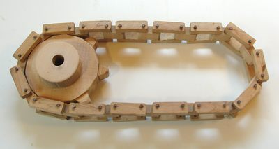 Block bondage are an older, obsolete style of drive chain. Block chains are much simpler to make, and lend themselves well to forest. In a block chain, the sprocket engages bocks in the heart of the chain. Each cake has two holes, to which the links on either side attach. An instance use of a wooden block chain can be seen in this tank thread vehicle
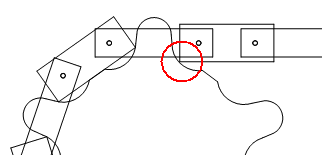 If the blocks of a block concatenation are not rounded on the corners, then the corners tend to scrape the sprocket where the chain engages and disengages the sprocket.
The gear template generator will generate sprocket shapes that make allowances for this "undercut" side by side to the teeth for this, but the sprockets are still somewhat ugly and inefficient.
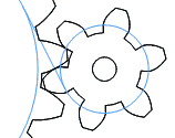
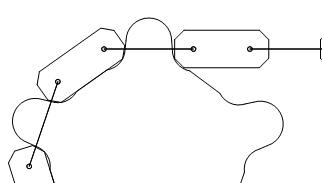 A much better solution is to put a scrap of a round or chamfer on the edges of the chain blocks. The sprocket at left is very like to the previous sprocket, but with blocks that have chamfered corners. Note that the teeth accept much less undercut.
For clarity, I inverse the links to be very thin, but the links exercise non actually engage the sprocket, so only the link'due south length, non its bodily shape contributes to the sprocket shape.
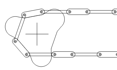 The gear generator can generate shapes for workable sprockets down to three teeth. However, these sprockets are inefficient and will run very rough. If you use the "Animate" role in the gear template generator, you tin meet that the chain has quite a scrap of side-to-side motion.
The shape of the teeth also doesn't engage the chain very well, as the teeth need to be very sloped to permit the chain to appoint and disengage the sprocket.
 Sprockets with larger number of teeth will run much more smoothly.
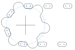
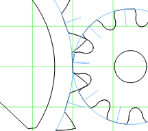
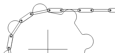
 To better see how the chain meshes, parts of the chain and sprocket can be hidden. The epitome at left, for example, has the chain links hidden. Yous can likewise hide the chain entirely. Hiding the chain is useful when making a printout of the sprocket template shape to use when cutting the sprocket out of plywood.
The image at left also has the "Show pitch diameter" turned on. The blue lines stand for the pitch bore, and the lines crossing it betoken the centers of the tooth undercut radii. If you have the right size drill, you can commencement by drilling out the undercut circles, which will make it easier to cut out the residue of the sprocket with a bandsaw
Specifying the concatenation dimensions
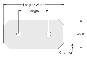 The shape of the sprocket teeth is generated based on the shape of the chain blocks, and the length of the concatenation links.
 The shape of the chain blocks and links is specified in terms of length and width. Please note that the specified length is the length between the 2 holes. The programme automatically adds some length to the link to let for material around the holes.
An additional parameter, "Chamfer" determines how much to remove from each corner of the blocks and links. If "Round chamfers" is selected, the chamfer is replaced by a round with a radius equal to the chamfer measure.
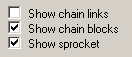
Display parameters

This part of the panel selects which aspects of a gear to display.
Show pitch diameter
When selected, a circle is drawn indicating the gear'due south pitch diameter.
Show line of contact
For involute teeth, this shows the contact angle (pressure angle) and base radii of the two gears. If you think of the base radii equally being ii spools, a point along a string unwound from the right gear'due south base radius and wound onto the left gear'due south base of operations radius would exactly follow the path forth which both gears bear upon.
Show middle
Bear witness a crosshair in the middle of each gear.
Depict thicker lines
Doubles the thickness of lines used to draw the gear, so that the lines bear witness upwardly better on printouts.
Draw unmeshed
If both gears fit on ane page, select this option to draw the gears separated so that when you print them, you can cut the ii shapes out separately. Also useful for CAD exporting both gears at the aforementioned time.
Fewer line segments
Approximate the circular curves of the gears with fewer line segments. The departure is non noticeable at a glance, but when exporting and importing into other programs, some programs have difficulty with the number of line segments that the gear program creates.
Grid
Draw a grid. The grid is useful for getting a sense of scale, for checking that a printout was scaled correctly, and to help marshal multiple pages together when pasting together multi-page printouts.
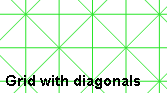
Grid diagonals
Draw diagonal lines on the grid. Diagonal lines are very useful to help align the sheets of a multi-folio printout when gluing the pieces of newspaper together. The diagonals grids work so well, I later on wrote BigPrint to allow other types of images to be pasted together this manner.
Animate
Slowly plow the gears. This allows you to examine how the gears mesh. Note that spur gears with less than 10 teeth and low contact angles volition ofttimes cause interference. For gears with very few teeth, try pinwheel gears.
Wobbly
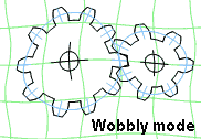
I implemented "wobbly style" for the evaluation version of the program. The eval version can exercise everything the full version can do, just all output is distorted. The distorted gears would not piece of work in existent life.
I found the distorted "wobbly mode" fun to watch, so I have added this "characteristic" as an option to the total version equally well, just for fun.
Testify rotated
This field causes the gears to be displayed rotated. The angle is specified as ane hundredths of a tooth. Specifying 25, for instance, will crusade the gears to be rotated by one quarter tooth interval.
This feature is useful if you lot want to check that spur gears mesh without interference. Information technology'south specially useful if you use the up/downwards buttons, and zoom in on the meshing point past reducing the value of the "screen view width" field.
Screen view width
This field indicates how broad an area the screen represents. This value defaults to twenty cm, or virtually the width of the printable region on a normal piece of paper.
Notation that this value is in whatsoever units y'all chose. If you alter the units to "inches" then the visible region would modify to xx inches, along with all other dimensions. The display would not change, just when you lot impress it, information technology will now be much larger as information technology's now sized in inches.
Saving
The parameters for a gear tin can be saved in a file for afterward reloading. The parameters are but stored in a text file. If a file chosen "default.gear" exists in the same directory as the program, information technology will be loaded automatically when the program starts.Units
Units tin can be selected to be inches, centimeters or millimeters. Notation that the displayed gear'southward size does not alter if the units are changed. A gear that is ten cm across, when y'all change the units to inches, will now exist x inches across. The screen width would likewise change from twenty cm to 20 inches. However, on printing or exporting, the gears will exist scaled appropriately. Note, however, that on importing DXF, the units are non specified inside the file. Typically, one must indicate to the importing program what units are represented in the file.Printing
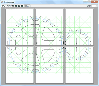 The gear template generator is able to impress gears that span many pages. If a gear does not fit onto a single folio, then the gear is split beyond multiple pages to be printed and then glued together.
 Grid lines, specially when combined with diagonal grid lines, are very useful to assist precisely align the pages when gluing them together.
It's advisable to practice a impress preview before printing your gears. The dimensions you accept specified might result in gears that bridge a surprisingly large number of pages.
Printing parameters
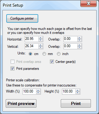
Printer scale scale
You may find that your printer prints simply slightly larger or smaller than it should, peculiarly if your printer is a laser printer. If yous discover that x filigree lines of a i centimeter grid are actually x.ane cm horizontally, you can compensate by setting the width calibration to 99%. If y'all switch to "landscape" orientation, the "width" is actually the length. The labels adjust to reverberate this.
Horizontal / vertical / overlap
If you impress gears that bridge multiple pages, the gears are printed with no overlap past default. You may prefer to take a slight corporeality of overlap from page to page to give you lot more confidence in aligning the pages. Yous tin can either enter the overlap, or you tin can enter the spacing of the pages. Note that the spacing and size of the pages e'er full upward to the printable area on a page.
Yous may also notice that its quite easy to align the pages even without overlap when grid diagonals are enabled.
Print overlap area
Y'all can select whether to print in the overlapped area. This selection is just enabled if an bodily overlap is selected using the horizontal/vertical/overlap fields.
Center gears
Normally, the gears are in the top left of the page, or group of pages. If you check this, the gears volition be centered on the page, or grouping of pages.
Print parameters
If checked, the actual gear parameters will be printed on the height left of the page.
Exporting
When exporting to a file, everything that is fatigued on the screen is exported. This included both gears, too as any center and filigree lines yous may have turned on. It's recommended that you turn off everything merely one gear and its center crosshair before exporting. Otherwise, it can be difficult to divide the gears from the grid in whatsoever program you are importing into.No printer pagination will be applied to consign.
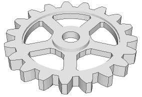
in SketchUp
DXF (with poylylines)
Almost CAD programs tin can import DXF files. The gear template generator's DXF export is relatively simplistic and only two dimensional, but information technology will go the shapes into your CAD program.The DXF consign does not include units. Programs that import DXF typically allow you to specify which units the DXF file actually uses. For example, if you lot used inches to design your gear, only the importing plan assumes the units are millimeters, the imported gear will be much smaller than y'all wait.
Please note that DXF export with polylines for version 3.0.x is less than perfect and that AutoCad will non successfully import this. Version 3.i improves DXF polyline export and works with AutoCad. Click on "help" in your program to update.
DXF (basic DXF)
DXF is a very difficult to figure out format, and the DXF exported by the gear template generator may not be compatible with all programs. If the "with polylines" export does not work, try exporting as basic DXF. Basic DXF exports line segments only. Unfortunately, this means some programs will non recognize the outline as a joined object.SketchUp
1 of the near popular CAD programs amidst woodworkers is the free SketchUp. However, the free version of SketchUp does not handle DXF import. Information technology does, however, import data in "Collada" format. Because and so many people use the complimentary version of SketchUp, I implemented export to this format and then that y'all can even so import gears into the gratuitous SketchUp. As CAD programs go, SketchUp is relatively easy. But be warned. All CAD programs have a steep learning curve.When you import a gear into SketchUp, it will be imported as nested objects. Keep opening the objects until you can select individual line segments of the gear outline. To turn the outline into a surface that can be extruded, describe a rectangle around the whole outline, and then delete the outline of the rectangle. If your gear has spoke and heart holes, select these with a double click, copy them, delete them, and so paste them in identify. Later on that, you lot will be able to delete the surface inside the spoke holes. I don't call back SketchUp works as well as they say information technology should in this item regard, only the in a higher place procedure has worked for me.
HPGL
HPGL stands for "Hewlett Packard Graphics Language". It is the format used by the former HP plotters. Nobody uses plotters anymore, but the format is adequately straightforward and various pieces of software still know how to import and export graphics in this format.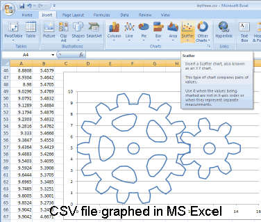
CSV (for spreadsheet)
CSV (Comma Separated Values) is the simplest form of export, consisting of just two columns of numbers, plus some notation. This format can be loaded into spreadsheets such as Excel. You can display the gears equally a graph in Excel past selecting the two columns of numbers and generating an 10-Y scatter graph from the data.Displaying gears in a spreadsheet is non particularly useful, but it's a good starting betoken if you wish to manipulate the X-Y points in some way for your own purposes.
Paradigm (bitmap)
Exports the epitome equally a bitmap (BMP, Jpeg, or PNG). A window will pop up allowing you to specify how many pixels per size unit (pixels per inch, per centimeter or per millimeter), and whether antialiasing (line smoothing) is turned on.If you need to create a PDF for printing across multiple pages on another printer, the best way to go along is to print to a file. To impress to a file, become to "configure printer" nether impress setup, and select "Microsoft XPS document..." as the printer. Then print. Windows will prompt you to specify a file to print to. Then upload the XPS file to http://world wide web.xps2pdf.org/ to convert it to a PDF file. Notation that this play a joke on works with any program that can print to a printer. No demand to install special software on your computer to create PDF files. There are also "printer drivers" available on the internet that allow you to impress directly to a PDF file on your computer, such as the gratuitous Bullzip PDF printer driver , merely printing to XPS and then converting doesn't require any extra software installation.
SVG
SVG stands for scalable vector graphics. Some newer laser cutters and CNC routers are able to import SVG. SVG was intended for screen graphics, and is sized in pixels. You have to enter how many "pixels" per unit of measurement your importing program expects. Otherwise, the object may not come out the right size. SVG export was added with version 3.ane.1, March 2015.
Any other questions?
If you have any questions almost the gear template generator that this Help doesn't reply, experience complimentary to electronic mail. Feedback is ever appreciated.My email address is:
More about the Gear template generator
Source: https://woodgears.ca/gear/help3/index.html
0 Response to "how to draw gear in autocad 3d"
Enviar um comentário